|
|
![]()
|
|
![]()
|
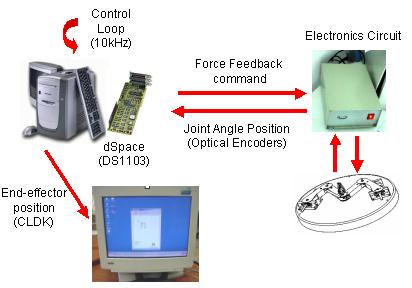
The control system architecture is based on a host PC Pentium II with OS Windows 2000 and a real-time board (dSpace: ds1003). The hardware system architecture is showed in Fig. 3. The software control schemes have been developed in MATLAB and Simulink environment, with Stateflow and RealTime Workshop toolboxes.
Figure 3 - Hardware System Architecture
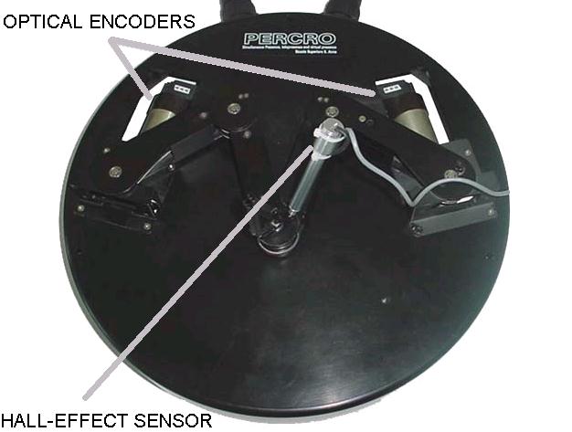
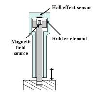
Haptic Interface A specific HI for handwriting has been developed at PERCRO (Frisoli, 1999). This interface is a parallel manipulator with a high kinematics and dynamics isotropy and large workspace respect to the device bulb. This HI is a parallel manipulator composed of two serial sub-chains with a high kinematics and dynamics isotropy and large workspace respect to the device bulb (namely a five bar mechanism but with a particular, high isotropic, actuation subsystem). Two optical encoders are used to measure the joint angle position of each motor (Figure 4). Using the CLDK algorithm (Control System section), the end-effector position is obtained to track the pen position. A Hall-effect sensor was attached to the pen-stylus to identify when the users is writing or not. A detail of the hall-effect sensor is shown in Fig. 5. The sensor measures the position of the pen respect to the base. This measure is based on the variation of the magnetic field respect to a magnetic source. The pen is free to move along its axis until a rubber element, placed between the magnetic source and the sensor, constrains its motion. This element provides a mechanical stiffness to the pen.
Figure 4 - Two optical encoders and a hall-effect sensor were mounted to the HI to be used as tracking systems.
Figure 5 - Detail of the Hall-effect sensor attached to the pen-stylus.
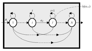
Recognition System The work of recognition system can be achieved with several techniques. Different algorithms exist to perform task recognition: Primitive Decomposition [Guberman, 1994], Motor Models [Hollerback, 1981], Deformation Models [Li, 1997], Hidden Markov Models [ Makhoul, 1994], Neuronal Networks [ Manke, 1994], etc. A Hidden Markov Models (HMM) has been successfully implemented in speech recognition [Huang, 1992], robot path planning simulations [Zhu, 1991], telemanipulation systems [Hannaford, 1990]. The main advantages of using HMM for the recognition system are principally three: 1. HMM is capable of characterizing online a doubly stochastic process with an underlying stochastic process (user's intentions) that, although immeasurable, can be measured through another set of stochastic process (resultant action); 2. HMM is a parametric model and its parameters can be optimized by efficient algorithms for accurate estimation; 3. HMM can represent all the training data in a statistic sense by its parameters, producing a full likelihood list. A HMM is a collection of finite states
connected by transitions. Each state is characterized by two sets of probabilities:
a transition probability, and a discrete output probability distribution
that defines the condition probability of emitting each output symbol
from a finite alphabet. The elements of an ergodic HMM used in our recognition
system are shown in Fig 5. A compact notation of a discrete HMM, to represent
the complete parameter set of the model, is given by Lambda= (A,B,Pi).
The learning in HMM is achieved by adjusting the model parameters, to
maximize the probability that the model matches with a given observation
(Rabanier, 1986).
Figure 6 - HMM elements
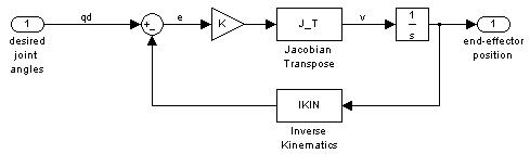
Control System The direct kinematics problem for a parallel robot consists of finding the vector of the end-effector position coordinates (x,y) as a function of the vector of joint variables (q). Siciliano (1999) proposed the closed-loop direct kinematics (CLDK) algorithm to solve this problem. Basically, the direct kinematics solution can be formulated as function of the joint motion through the inverse kinematics (Figure 7).
Figure 7 - The closed-loop direct kinematics (CLDK) is based on the transpose of the Jacobian matrix, using the inverse kinematics in the return path. Task Replication In our application, in order to replicate
a motion task, the trajectory has been defined by means of a point vector
Tv(K), where for each digital time step K, defines the associated sample
to the desired contact position. This supposes that the trajectory speed,
time and position dependences have been eliminated.
Consequently, we can define a simple control law as (where Kp and Kv represent the stiffness and damping factors):
Figure 8 - Predefined trajectory at the time K. The trajectory nearest contact point position
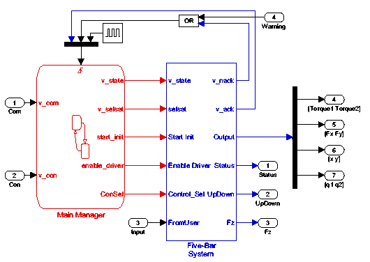
( The system is divided in five principal phases that are managed through a Stateflow machine (Figure 9): Off: In this phase, the control system is waiting for an initialization command from the application. All the system control outputs are disabled; Init: The initialization phase places the EF position to the center of the workspace, using an absolute reference given by the optical encoders attached to the motors. The EF-position was controlled using a PD control where the stiffness coefficient (Kp) was set to 900 N/rad and the damping coefficient (Kd) was set to 1 N-s/rad; Run (safe mode): This phase enables to the control designer to test the application without affecting the mechanics of the HI (the motor current output is saturated); Run: After the application was tested and improved, the system is ready for interacting with the user; Stop:
This phase is used when the user wish to finish the application. The control
system places again the EF in the center of the workspace. In case that
any warning signal is generated by the control, all the output signals
are disabled.
Figure 9 - A Stateflow machine controls all the system phases.
|