|
|
|
The Automated system for Ultrasound Liver Scanning |
|
|
| |
|
1.Background
2.Liver ultrasound diagnosis 3.System configuration 4.Evaluation test 5.Acknowledgment/link |
Papers
Takanishi Laboratory Home |
1.Background
Introduction
Purpose
2.Liver ultrasound diagnosis
Liver ultrasound diagnosis
|
ü@Robotic automated scanning protocol is designed based on the sonographers' textbook. |

Scanning protocol
|
Required specifications
|
ü@Required specifications are as follows. |
ü@ü@ü@ü@

Pivot Scanning
|
3.System configuration
Configuration
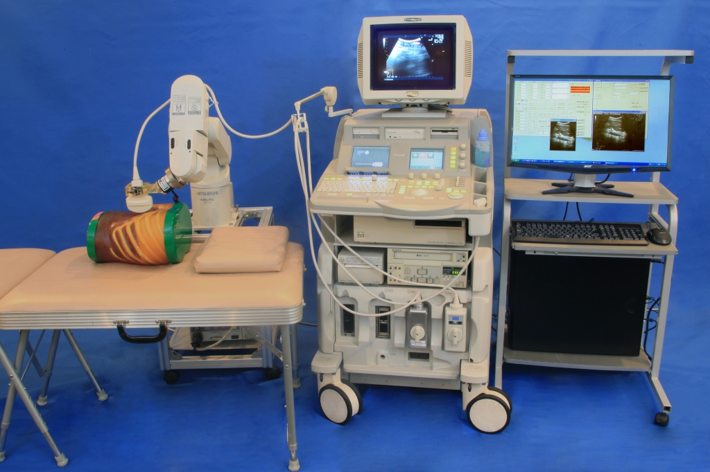
ü@The proposed system is composed of a 6-DOF industrial robot, a 6-axis force-torque sensor, an ultrasound diagnostic system, and PC.
ü@The overall view, block diagram are as the following figures.
ü@The four sequences in thescanning protocol and pivot scanning patterns are given by pattern generator.
ü@Robot detects the reaction force applied for the patient skin by the 6-axis force-torque sensor attached to edge of manipulator, and modify its trajectory to keep probe contacting to the patient skin by constant force control.
ü@Ultrasound images are captured by PC through video capture board. During the scanning, the probe posture is always adjusted if non-visible area appears in the ultrasound image, so that images are kept in the condition that doctor can diagnose.


üi1üjScanning protocol
|
ü@Several starting points in 6 axis are predefined according to the scanning protocol. |
||||||||||||||||||

Scanning protocol
üi2üjPress force control
ü@Probe has to be kept contacting to the patient body regardless to the individual body shape and movement of the body surface due to breathing.
üi3üjProbe angle adjustment
ü@If there is a gap between the left or right edge of probe and skin surface, a vertical dark zone in the ultrasound image appears in left or right part.
4.Evaluation testüi1üjConstant force control evaluation
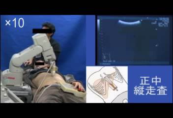
üi2üjValidation of the proposed system
˙@)Questionnaire
ü@Operation test has been applied for 1 healthy volunteer. Three clinicians (Doctor:1,Sonographer:2) were answered to the questionnaire. Questions are as follows. 
Questionnaire results
˙A)Unconfirmed region
ü@Three clinicians were asked to specify the unconfirmed region in the liver by marking in the drawing of the liver (see figure). 
Unconfirmed region
üi3üjConsideration
5.Acknowledgment/link
We would like to express our thanks to Prof. Saito of Tokyo Women's Medical Univ.Prof., Sugawara of Himeji Dokkyo Univ.,
Prof. Niki of Tokyo City Univ. and Hitachi Aloka Medical,Ltd. for their daily suggestions and supports.
And also thanks to SolidWorks Corp. for their support of CAD software.
| ||||||||||||||||||


 Tokyo City University
 Hitachi Aloka Medical,Ltd.
 SolidWorks Corp.