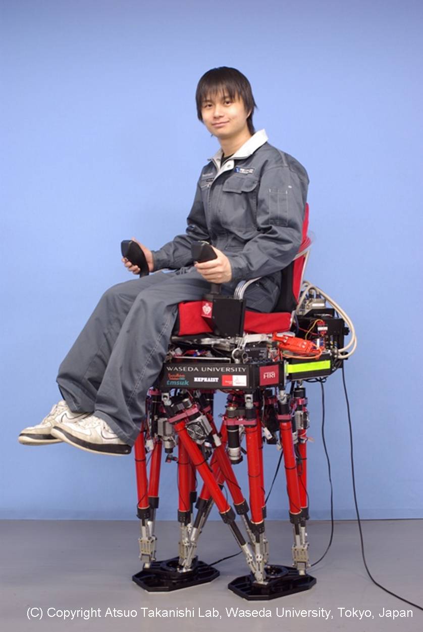
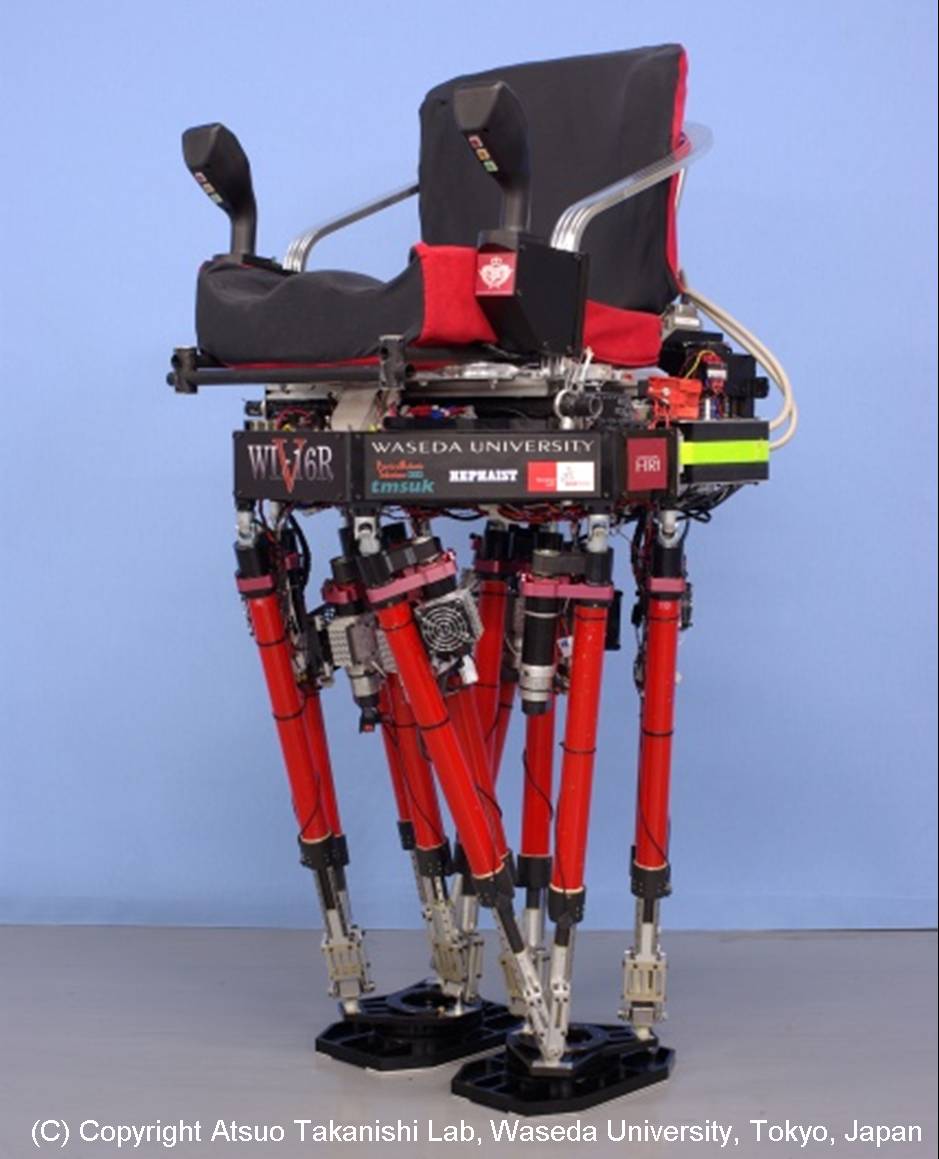
Multi Purpose Biped Locomotor
WL-16RV
Waseda Leg - No.16 Refined V
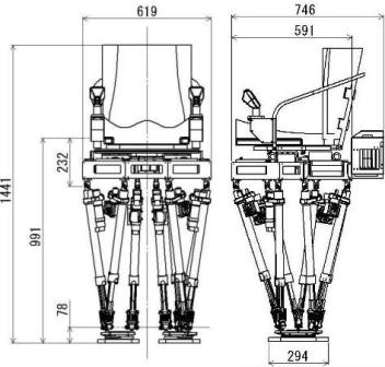
Specification of WL-16RV
As legs of WL-16RV, we have adopted a pair of 6-DOF parallel mechanisms. And WL-16RV consists of two legs and a waist, and can walk independently. As for details, please refer to WL-16.
The specification of WL-16RV is following.
 |
 |
| ��Size & Weight | |
| Height [mm] | 1431 |
| Weight(without Battery) [kg] | 61 |
| Total Weight [kg] | 75 |
| ��Mechanism | |
| Link Mechanism | Stewart Platform |
| D.O.F | 6DOF x 2Legs = 12 |
| ��Motor | |
| Motor | DC Servo Motor x 8 AC Servo Motor x 4 |
| Rated Output [W] | 150(DC) 200(AC) |
| >��Electric Equipment | |
| CPU | Pentium�V 1.2[GHz] |
| Battery | Li-ion Battery |
| Sensors | �@�E Force / Torque Sensor x 3 �@�E 3 Axis Angle Detector x 1 �@�E Rotary Encoders x 12 �@�E Photomicrosensor x 12 |
| ��Specification | |
| Walking Cycle [s/step] | 0.8 �` 2.0 |
| Step Length [mm/step] | 0�`300 |
| Loading Capacity [kg] | 70 |
��TOP Page
Improvement of operating time by cooling motor
�P�DResearch Purpose
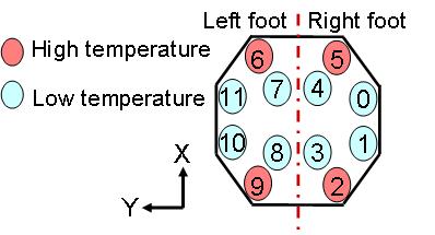
WL-16RIV has 6-DOF parallel mechanism legs based on Stewart Platform, but the load of each linear actuator is not even. The operating time depended on not battery capacity but motor heating of heavily-loaded motors. So, we developed a motor cooling mechanism which consists of heatsink and fan. Additionally, we changed heavily-loaded motors from DC motor to brushless motor, because the motor-winding of brushless motor has better cooling efficiency than that of DC motor.
 |
|
Fig .1 Link arrangement |
��TOP Page
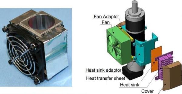
�Q�DMotor Cooling Mecanism
There are various cooling mehtods, heat sink, fan, heat pipe, peltiert device, water cooling and etc. I chosed fan and heat sink as motor cooling method becaese they are light and low energy.
 |
|
Fig .2 Motor Cooling Mechanism |
��TOP Page
�R�DTesting Machine
We developed testing machine because cooling experiment did not have repetability. This reason was model error of robot and raod surface.
|
Overview |
��TOP Page
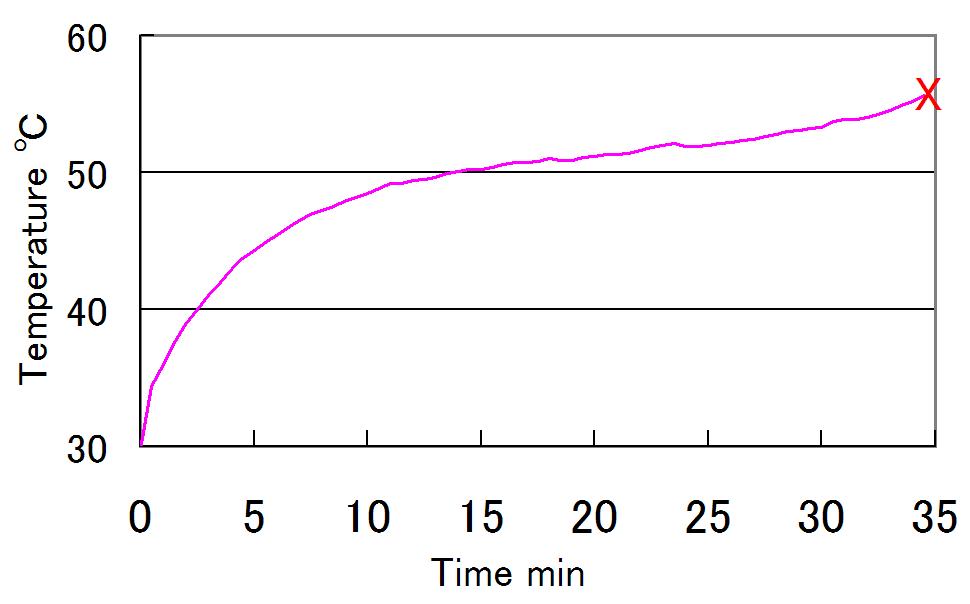
�S�DMotor Change
Even if motor housing was cooled down,it was difficult to cool motor coil because of the air between the motor coil and housing. We decided to changed motors which because it was difficult to cool DC motor whenWL-16RIV carries 80kg payload
 |
|
Fig .3 Temperature of Motor Sueface |
��TOP Page
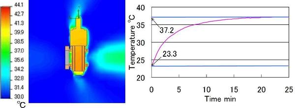
�T�DFan Selection by Thermo-fluid Analysis
Fans were selected by Thermo-fluid Analysis�DRange of temperature rise in simulation was almost same as result of cooling experiment by testing machine.
Experiment condition�@�ˁ@Payload�F80kg�CWalking pattern�FUp stair
 |
|
Fig .4
Result of Simulation |
��TOP Page
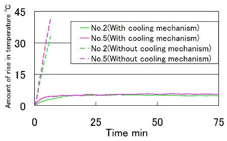
�U�DEvaluation Experiment
WL-16RV succeeded to walk for 75[min] by using motor cooling mechanisim with 70[kg] loaded!
Experiment condition��Payload:70[kg],Walking pattern:Stamping
 |
|
Fig .5
Comparison of Motor Housing Temperature |
��TOP Page
Terrain-Adaptive Control with Small Landing Impact Force
�P�DResearch Purpose
We proposed a landing pattern modification method not using any other sensor information except force sensor's information. But it has a problem that a foot landing-impact increases when a walking cycle is short. It is difficult to achieve a good balance between a terrain adaptation and a landing-impact force reduction on uneven terrain. So,we developed a new terrain-adaptive control reducing a landing-impact force. The walking technology consists of the following five key points:
|
|
Foot Level Modification |
|
|
Changing a position gain value for motor drivers |
|
|
Foot speed control after detecting a foot landing |
|
|
Adaptive motion about roll and pitch axes |
|
|
Returning motion to a reference walking pattern at every step |
|
| Foot Level Modification |
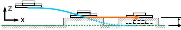
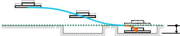
The previous method(Landing Pattern Modification Controll) had a problem that it was difficult to achieve a balance between a terrain adaptation and a landing-impact force reduction especially on a concave surface. So, we devised a new foot level modification method to deal with not only a convex surface but also a concave terrain. We set a target landing position beneath a reference level as shown in Fig .6 to adapt to a concave surface.
|
| (a) Previous landing pattern modification method. |
|
|
(b)
New terrain-adaptive control with small landing impact force. Fig .6 Foot adaptation to concave surface. |
|
| Changing a Position Gain Value for Motor Drivers |
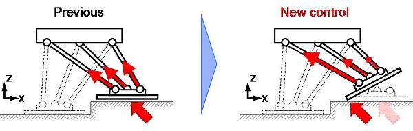
We realized a high compliance of the landing foot by actively decreasing a position gain value for motor drivers in a swing phase. On the other hand, the leg mechanism of WL-16RV consists of a parallel linkage mechanism called the Stewart Platform, so it is difficult to obtain a high compliance of the landing-foot only by changing a position gain value as mentioned above. Therefore, we realized a larger position following error by raising the foot's edge of the traveling direction and concentrating a landing-impact force to an actuator nearest to a contact area as shown in Fig .7. As a result, we could obtain a higher compliance against an external force.
|
| Fig .7 Impact force reduction considering the leg's mechanism |
|
|
Foot Speed Control after Detecting a Foot Landing |
To detect a foot landing on a ground, we focus attention on the force data measured by a 6-axis force/torque sensor mounted on a foot. A foot landing is detected by the differential value of the force data along z axis. The advantage to use the differential value is an ignorable sensor drift and a fast landing detection. When detecting a foot landing, the foot speed is changed to zero under the law of conservation of momentum.
|
| Adaptive Motion about Roll and Pitch Axes |
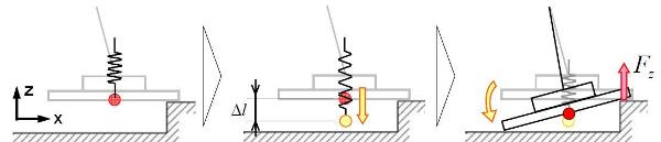
The adaptive motion about roll and pitch axes is not completed because the foot speed is changed to zero and the foot level is fixed after detecting a foot landing on a ground. Therefore, to realize a terrain-adaptive motion, we firstly installed a virtual compliance control to the z axis of a robot's feet. As a result, the virtual compliance control presses a swing foot toward the ground at a constant load. By utilizing the moment generated by the pressing load, we applied a virtual compliance control to the roll and pitch axes of a robot's feet, and a terrain-adaptive motion is realized as shown in Fig .8.
|
| Fig .8 Adaptive motion about roll and pitch axes. |
|
|
Returning Motion to a Reference Walking Pattern at Every Step. |
The roll and pitch compliance displacement obtained in the end of a swing phase is held during the stance phase, and the roll and pitch foot motion returns to the reference walking pattern in the first half of a swing phase.
��TOP Page2.Evaluation Experiment
WL-16RV realized a stable walk on uneven terrain and a human-carrying walking at outdoors by this research. The outdoor walking experiment was conducted to walk down the slope with about 7 degrees inclination.
|
Walking experiment on uneven terrain. Walking Cycle�F1.0 [sec/step] Step Length�F200 [mm] |
|
Walking experiment outdoors. Walking Cycle�F2.0�@[sec/step] Step Length�F200 [mm] Incline�F7 [deg] |
��TOP Page
Dynamic Disturbance Compensation Controlor
�P�DResearch Purpose
Since a walking pattern is previously generated offline, it makes the locomotor unstable when external force acts on it. In this research, we aim to develop a new stabilization control under unknown external disturbance caused by passenger's active dynamic motion. This disturbance compensation control consists of the following three key points:
|
|
Waist trajectory computation |
|
|
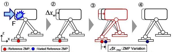
Reference ZMP Variation |
|
|
Landing point variation computation |
|
|
Waist trajectory computation |
When unknown external force acts on a walking robot, first the robot accelerates the waist so that a measured ZMP is equal to a reference ZMP. To compute the waist trajectory, we define the biped walking robot system as an approximation model that has one particle for the waist including a passenger and two particles for the feet as shown in Fig .9.

|
| Fig .9 Definition of coordinate systems and vectors. |
|
| Reference ZMP Variation |
Reference ZMP is changed by multiplying a proportional gain by the deviation between a reference and an actual waist trajectory. By generating a compensation trajectory around a varied reference ZMP, the divergence of a waist motion can be delayed and inhibited.
|
| Fig .10 Reference ZMP variation |
|
| Landing Point Variation Computation |
When the waist trajectory does not converge with only reference ZMP variation, the divergence can be inhibited by changing a ZMP trajectory and a foot-landing point. To compute the landing point variation, we use a one particle model for the waist as shown in Fig .11.
.jpg)
|
| Fig .11 Approximate model (1-particle) |
2.Evaluation Experiment
We did fundamental experiments that a human pulled the robot carrying no loads forward and sideways while WL stepped and walked forward. WL realized a stable walk under such an external force.
|
Disturbance Experiment(Foward) Walking Cycle�F1.0�@[sec/step] Stamping |
|
Disturbance Experiment(Sideway) Walking Cycle�F1.0�@[sec/step] Stamping |
|
Disturbance Experiment with carrying a 50 kg human Walking Cycle�F1.0�@[sec/step] Step Length�F100 [mm] |
Static Disturbance Compensation Control
�P�DResearch Purpose
Since a walking pattern is previously generated offline, it makes the locomotor unstable when external force acts on it. In this research, we aim to develop a new stabilization control under unknown external disturbance caused by passenger's static motion. This disturbance compensation control consists of the following three key points:
|
|
Waist trajectory computation |
|
|
Calculation of the target external force |
|
|
Target ZMP deviation computation |
|
| Waist trajectory computation |
When unknown external force acts on a walking robot, the robot accelerates the waist so that a measured ZMP is equal to a reference ZMP. To compute the waist trajectory, we define the biped walking robot system as an approximation model as shown in Fig. 12(Same as Dynamic Disturbance Compensation Controlfor).
|
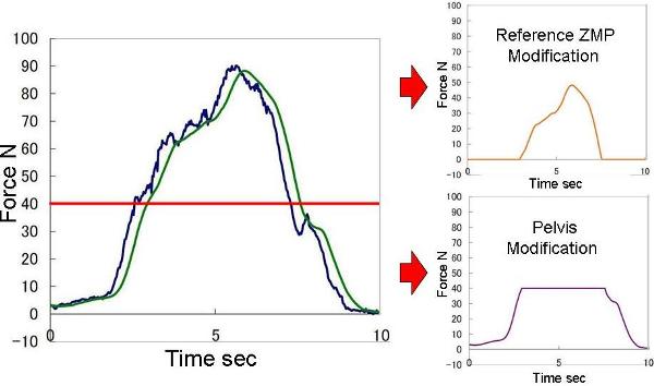
| Calculation of the target external force |
To measure forces and moments caused by a passenger's motion, we use a 6-axis force/torque sensor placed between the passenger's seat and the pelvis. the measured force vibrates, so the modification value also vibrates to compensate for external forces, and a biped robot becomes unstable. We solved the problem by using an average force. The compensation trajectory is computed based on this target force.
|
| Fig .12 Modification of Force |
|
| Target ZMP deviation computation |
The proposed control is a "static" disturbance compensation control, so this control cannot deal with rapid changes of external force. Combining static and dynamic disturbance compensation control, however, a waist deviation should be small from the viewpoint of a robot's walking stability. So when small external force acts on a robot, a reference ZMP trajectory is changed inside a support polygon without changing a waist motion.
|
| Fig .13 Target Force Divided to Two Parts |
2.Evaluation Experiment
�@By static disturbance compensation controlfor, WL succeeded to walk even if a human slowly pulled the robot forward. And we did walking experiments by combining the static disturbance compensation control with the dynamic disturbance compensation control. First, a human pulled the robot slowly, and lost the hold on the wire suddenly. The robot equipped a level meter made of LEDs. One line represents 10 N, and it can show up to 100 N.
|
Disturbance Experiment�iForward�j Walking Cycle�F1.0�@[sec/step] Stamping |
|
Disturbance Experiment�iForward�j �iCombine Dynamic Disturbance Compensation Control�j Walking Cycle�F1.0�@[sec/step] Stamping |
|
Disturbance Experiment by a Passenger �iCombine Dynamic Disturbance Compensation Control�j Walking Cycle�F1.0�@[sec/step] Step Length�F200 [mm] |
Recection Control of Disturbance from Environment
1�DGoal of research
In our research we not only focus on the external disturbances coming from the robot's passenger,
but also on those coming from the environment. In order to compensate for disturbances, we first
estimate the size of disturbance from ZMP deviation and then modify the motion pattern accordingly.
The basic algorithm comprises of the following steps:
|
|
Estimation of disturbance |
|
|
Calculation of waist compensation trajectory |
|
|
Modification of foot landing position |
|
|
Modification of MZP trajectory |
|
|
Estimation of disturbance |
We use 6-axis force/moment sensor to detect the value of disturbance coming from the environment. By first calculating the difference between theoretical ZMP and calculated ZMP and then approximating our robot with a single mass model (see Fig. 11), we can calculate the magnitude of the external disturbance.
|
|
Calculation of waist compensation trajectory |
In order to prevent robot from falling, when subjected to external disturbance, we accelerate the waist of the robot to make collinear measured ZMP and calculated ZMP with included disturbance effect. The new waist trajectory is calculated from the moment acting around ZMP of the simplified 3-particles model (see Fig. 9). Since the solution diverges, we additionally modify the feet landing positions and ZMP trajectory.
|
|
Modification of foot landing position |
By modifying the landing pattern of the feet we constrain the divergence of waist trajectory. We calculate the landing pattern based on the single mass model as seen on Fig. 11.
|
| Modification of ZMP trajectory |
We calculate the modified ZMP trajectory by multiplying deviation from the waist trajectory pattern by gain. By generating the new waist trajectory based on the modified ZMP trajectory we create the motion where the waist trajectory converges (see Fig. 10).
TOP Page2.Experiments
We performed series of experiments to verifying the performance of the algorithms. In the first set we were pulling stepping robot from different directions. In all cases the robot changed the waist trajectory to comply with the disturbance. In the second set of experiments we were pushing a robot walking with passenger. Also in these cases the compensation control effectively modified the waist trajectory to comply with the disturbance.
|
Disturbance experiment�iWalking direction�j Video of experiment where a human applies external disturbance to the waist from the robot's walking direction, while robot is stepping in one place. Gait cycle�F1.0�@[sec/step] Stepping in the place |
|
Disturbance experiment with human boarding the robot (Walking direction�j Video of experiment where a human applies external disturbance to the waist from the robot's walking direction, while robot walks forward Gait cycle�F1.0�@[sec/step] Step length�F100 [mm] |
�ETOP Page