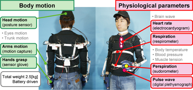
Fig.2.1 System Overview of WB-1R
Personal robots and robot technology (RT)-based assistive devices are expected to play a major role in our elderly-dominated society, with an active participation to joint works and community life with humans, as partner and as friends for us. In particular, personal robots must not have bad effect on human, neither physically nor psychologically. However, the psychological effect of robots on human has not been objectively measured. Among the other things, we considered that the motion of head and hands, which indicate emotion and consciousness, would change depending on the user psycological conditions. Therefore, we developed the bioinstrumentation system WB-1R (Waseda Boinstrumentation system no.1 Refined) which can measure the movements of the head, the arms, the hands, and several phisiological parameters, in order to objectively measure the psychological effect of robots on human. In this page we present the head and hands modules.
The bioinstrumentation system WB-1R consists of the motion capture (head, arms, hands), elecrocardiograph, digital plethysmograph, respirometer, and sudorometer. It weighs 2.5[kg], and is driven by batteries.
Fig.2.1 System Overview of WB-1R
We put an important point for price reduction and miniaturization and developed a posture measurement module which consists of acceleration sensors, a rate gyro, and geomagnetic sensors.
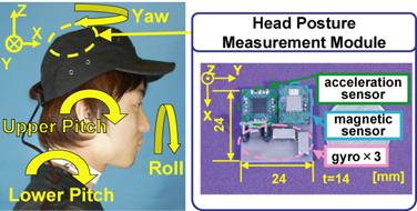
Fig.2.2 Head Posture Measurement Module |
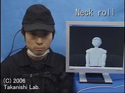
Movie of Head Motion |
The arms motion capture is the mechanical type and has a serial link mechanism with a potentiometer at each joint. It has 24-DOFs which consists of 6-DOFs from the back origin to the shoulder and 6-DOFs from the shoulder to the wrist in order to follow the movement of the shoulders rotation center.
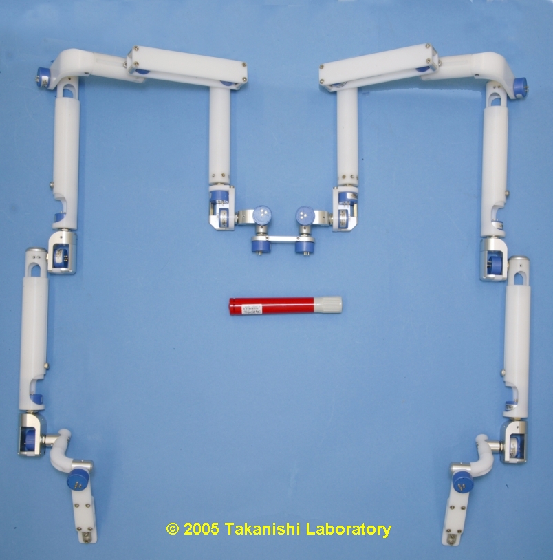
Fig. 2.3 Motion Capture Overview |
Video of Motion Capture |
We put an important point for price reduction and developed a 15-DOFs sensor glove using bend sensors.
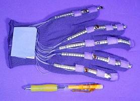
Fig.2.4 Sensor Glove |
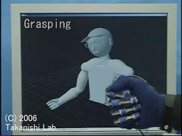
Movie of Hand Motion |
The electrocardiograph measures tiny current produced by the heart by applying electrodes to the body surface. Electrodes were pasted on the sternum which has few muscles, not to be affected by other myoelectric activities. The heart rate is calculated by setting a threshold as shown in Fig. 2.6.
Fig. 2.5 Location of electrodes |
Fig. 2.6 ECG(at rest) |
The light of LED is irradiated to the little finger. The digital plethysmograph measures the transmitted light by using photodiode, and so the blood flow is obtained.
In addition, we can calculate PWTT(Pulse Wave Transit Time) from the pulse wave and ECG. PWTT shows the relative change of blood pressure.
Fig. 2.7 Measurement method of pulse wave |
Fig. 2.8 Pulse Wave(at rest) |
Fig. 2.9 PWTT
The rubber band, on which the strain gauge is put, is wound around the chest and the abdomen. The respirometers measure both thoracic and abdominal respiration.
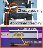
Fig. 2.10 Respirometer |
Fig. 2.11 Respiration(at rest) |
Electrodes are put on forefinger and middle finger. Sudorometer measures the skin resistance change by applying the tiny current to the electrodes. We can obtain the mental sweating on the palm.
Fig. 2.12 Location of electrodes |
Fig. 2.13 Perspiration |
Each measured data is converted from analog data to digital data by a PIC and is sent to a PC by RS232.
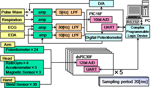
Fig. 3.1 System Configuration
Part of this reserch was conducted at the Humanoid Robotics Institute (HRI), Waseda University. We would like to thank Italian Ministry of Foreign Affairs General Direction for Cultural Promotion and Cooporation, for its support to the establishment of the ROBOCASA laboratory and for the realization of the two artificial hands. And part of this was supported by a Grant-in-Aid for the WABOT-HOUSE Project by Gifu Prefecture. Finally, We would like to express thanks to ARTS Lab, SolidWorks Corp., Advanced Reserch Institute for Science and Engineering of Waseda University, Prof. Hiroshi Kimura for this supports to our reserch.
Last Update: 2006-11-01