
|
|
|
Robot System for Carotid Ultrasound Diagnosis WTA-2R |
|
|
Waseda Tokyo Women's Medical Aloka
Blood Flow Measurement Robot System No.2 Refined |
|
|
1.Background
2.Hardware configuration 3.Automated positioning algorithm 4.Evaluation test 5.Acknowledgment/Link |
Robot assist system for abdominal ultrasound
Papers Takanishi Laboratory Home |
1.Background
The cause of Japanese death
|
ü@About 60 percent of the Japanese causes of death are the neoplasm (cancer), the cardiac disease (cardiopathy),
and the brain blood vessel disease (apoplexy), which are the three major lifestyle-related illnesses.(right fig) |

2009,Japanese causes of death
(Ministry of Health, Labor and Welfare) |
Wave Intensity
|
ü@Wave Intensity is an hemodynamic index which originally Paker and Jones proposed as an index
which can compare the influence of the forward and backward waveform of the blood pressure.
Although WI which came to be called such from it being the same unit as the intensity of a sound wave attracted attention only from the physical meaning,
superiority or inferiority of the influence of an advance wave and a reflective wave,
which the mark of the positive/negative has it becomes clear that the size of WI has an important physiological meaning
by the research of Professor Sugawara of the Himeji Dokkyo University,
and it attracts attention as a new indicator of blood-flow dynamics. ü@The arteriosclerosis will affect the size of compression wave (W1) of the right figure, and expansion wave (W2). W1 tends to be lower, and W2 tends to be higher with the progress of the arteriosclerosis. W1 and W2 are defined as the following formula. 
|

Blood pressure and speed

Wave Intensity
|
The problem of WI measurement and the purpose of this study
ü@During the WI measurement, the ultrasound probe is supported by hand or by the passive supporting devices.
However, maintaining the probe at small spot on carotid artery during WI measurement is difficult.
The load for the sonographer is large, and positioning reproducibility is problem.
In the case of using a passive supporting devices, the position-keeping load is small.
However, because of low user-friendliness, realignment takes time.
ü@The purpose of this study is to reduce the measurement time and the doctor's and the patient's fatigue by development of a robot system
and also implemented a automated positioning algorithm for the ultrasound probe on to the carotid artery by means of the image feedback.
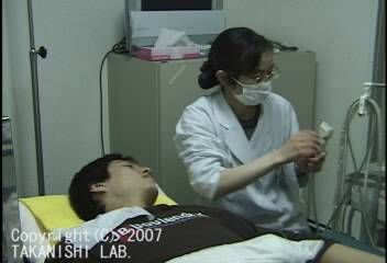
Click here to view the movie
WI measurement by hand |
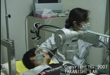
Click here to view the movie
WI measurement by a passive probe holder |
2.Hardware configuration
WTA-2R configuration
ü@The robot system for ultrasound diagnosis (WTA-2R) is composed of a probe hold robot,
a controller, a ultrasound diagnostic system, and a control PC. The overall view is as the following figure.
ü@The probe hold robot can change the end-effectors in three ways, the probe holding manipulator with the parallel link mechanism
for blood flow measurement (probe holding manipulator), the push support mechanism,
and the arm support mechanism.

üi1üjProbe holding robot

Probe holding robot
|
Approximate adjustment 
DOFs layout
|
˙@) Probe holding manipulator
|
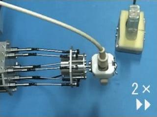
ü@The probe holding manipulator has 6-DOF, linear parallel link mechanism, and a probe holding device is attached in the end.
It is similar to the Stewart platform. The different point is that the actuator part is not inside the link.
By this configuration, the link diameter can be smaller, which reduces the interference between links. |
|

Probe holding manipulator
Actuator partü@The actuator part is composed of the DC motor and the ball screw, and the ball spline. The link part is composed a linear actuator (1-DOF), universal joint (2-DOF), and spherical rolling joint (3-DOF). The thickness of the link is 4[mm], and a movable angle of universal joint and spherical rolling joint are 45 [deg]. |

Actuator part
|
˙A) Probe holding device
|
ü@The objective of the probe holding device is to fix the ultrasound probe to the end-effector.
1-DOF rotational joint is required for adjusting initial angle between probe and manipulator.
The probe holding device is composed of the gear and the board spring, and can be fixed by the board spring engages in the gear.
The movable angle of X-axis rotation is ü}45[deg] with step of 10[deg] which is the distance of each teeth of the gear. |

Probe holding device
|
˙B) Positioning arm
ü@The positioning arm is passive and it has 6-DOF. It is possible to fix with the permanent magnet brake in each joint.
The positioning arm equips a gravity compensation mechanism configured with a constant force spring.
ü@The magnetic brakes can be locked and unlocked by a foot switch controller.
The magnetic brakes unlock the joints when power supply is on,
so that risk of injury to the patient (in case of an accidental shut down of the system) can be minimized.
ü@The fixing force of the arm is not strong so that a patient or a doctor can quickly change the arm's configuration
when a patient or a doctor feels danger. In this way, the arm assure the safety of the doctor and the patient.
ü@The gravity compensation mechanism is composed of constant force spring attached to slide guide so that moment arm of both side can balance.
Furthermore, slide guide has an adjustable small angle in order to cancel non-linearity of constant force spring output.
The mechanism achieved almost complete gravity compensation.

Positioning arm
|

The mechanical gravity canceller
|
üi2üjProbe controller
ü@Laser mouse sensors, acceleration sensors, rate gyro sensors and photo-reflector are used for probe controller.
X and Y-axis is detected with Laser mouse sensor. Yaw-axis is detected with two laser mouse sensors combination.
Roll and pitch-axes are detected with acceleration sensors and gyro sensors. Z-axis is detected with photo-reflector.
Controller is divided into grip part and base part so that laser mouse sensor should not leave from ground while the stick part has tilt angle.
ü@The controller can communicate with PC via USB connection to use microcontroller.


Probe controller
|
Click here to view the movie
Master slave movement |
üi3üjMotor driver
ü@In order to drive 6 DC motors in the manipulator, we have developed a small size, 6 axes,
position/velocity/current control motor driver. This driver can communicate with PC via USB connection.
The number of the cables in the system has been significantly reduced by using this driver.

Motor driver
|

Motor driver circuit configuration
|
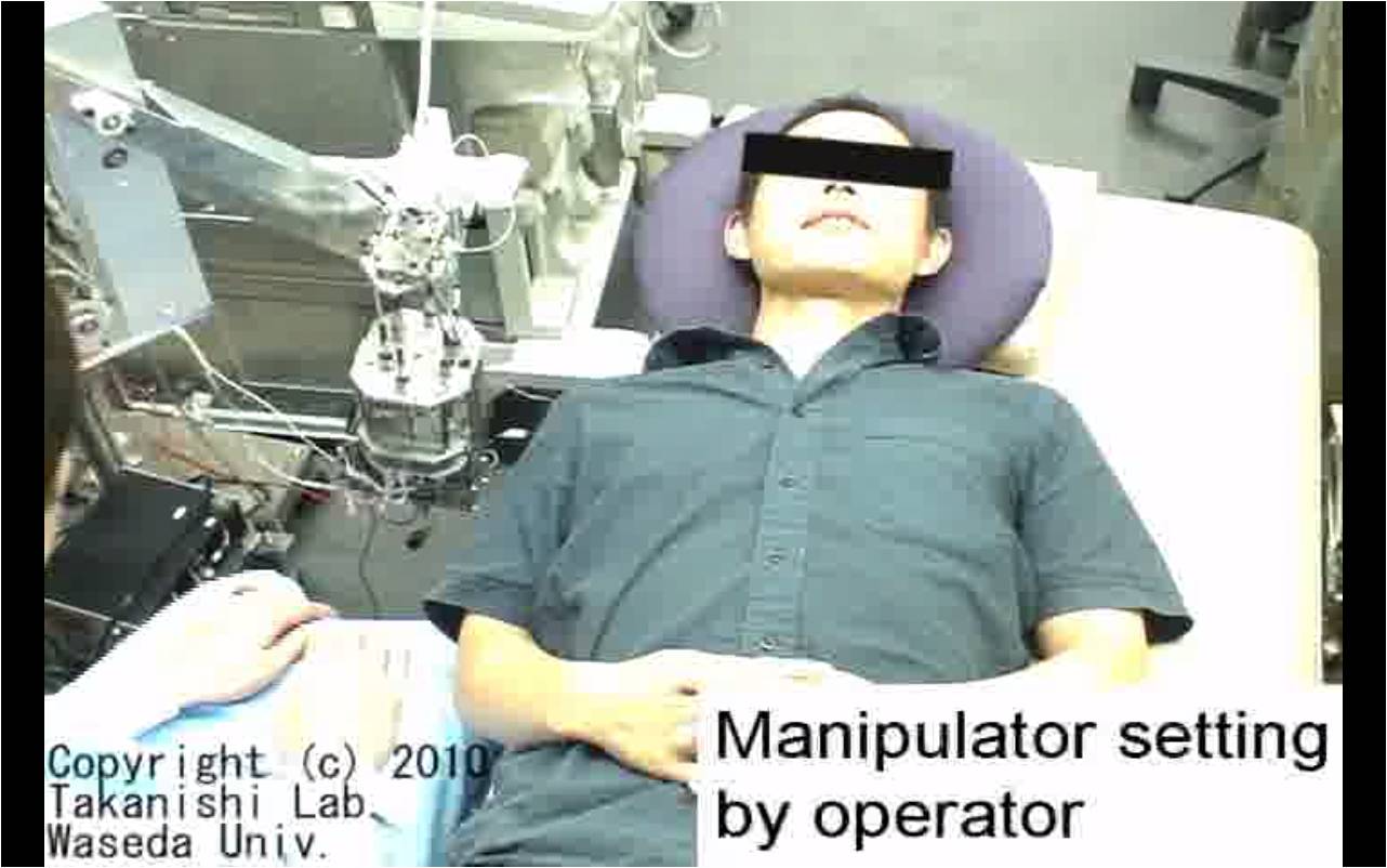
3.Automated positioning algorithm for the ultrasound probe
ü@Our robot system was originally developed as a master-slave robot. However, the doctors are busy for measurement itself rather than manipulating the robot. Therefore, we implemented a automated positioning algorithm for the ultrasound probe on to the carotid artery by means of the image feedback. The goal of the system is to be able to automatically obtain the ultrasound image suitable for the WI measurement (defined ü@as following 1-4) and recover the image when missing. Only the operator has to do is to locate the manipulator close to the patient neck.
The required image for WI measurement

The required image for WI measurement
|
1. The longitudinal section of the carotid artery is clearly observed |
The detection of the carotid artery
The longitudinal section of the carotid artery in the ultrasound image is observed as dark gap between parallel two white lines.
Usually they are straight, however sometimes bending.
They can be detected by scanning the image vertically because the carotid artery is always transversal in the image.
There are many high intensity lines in the ultrasound image but flat dark gap is almost the lumen of the carotid artery.
Therefore we have designed the algorithm to detect the transversal flat dark gap in the image.
(b).jpg "The detection of the carotid artery(a)(b)")
The detection of the carotid artery
üileftüF(a),rightüF(b)üj |
Algorithm
1. scan pixels along with the vertical lines set at regular interval,
then extract the dark gap by applying intensity threshold. (Fig (a)) |
The detection of the intima
|
ü@This is required for confirming that the probe is at the exact center of the artery. The artery wall has 3 layers, adventitia, media intima (from outside to inside). In the ultrasound image, the adventitia and intima are shown as white lines, and media is a dark line. However, intima is observed only when the ultrasound beam hits the artery walls in right angle. That is why the intima observation is used for the confirmation of the right positioning of the probe. Diameter of the artery is tracked during the WI measurement, therefore slight deviation from the center of the artery causes an inaccuracy of the measurement. The algorithm of the intima detection is developed based on the intensity gradient of the pixels around the detected artery walls. |

The detection of the intima
|
Designed movement of the probe
|
We have designed the sequential pattern of the probe movement as follows; |
||

Defining the points on the patient neck
|

Adjustment of the probe orientation
|

Detection of the vein
|
|
5. Detection of the bifurcation |
||

Inclination of the artery in the image
|
Click here to view the movie
Full sequence of automated positioning |
|
4.Evaluation test
üi1üjPositioning accuracy experiment
|
ü@The objective of positioning accuracy experiment is to verify the positioning accuracy of new manipulator
by using optical 3D tracker "Optotrack". |

Absolute positioning accuracy error margin result
|
üi2üjOperability experimentüiMaster slave operationüj
|
ü@The objective is operability experiment is to measure the time consumption of the probe positioning
and to obtain the sonographers' opinions.
5 sonographers tried to position the probe on the carotid artery with this robot (WTA-2R) and the old model (WTA-2).
The time consumption for the positioning both |
Click here to view the movie
Master-slave operation |
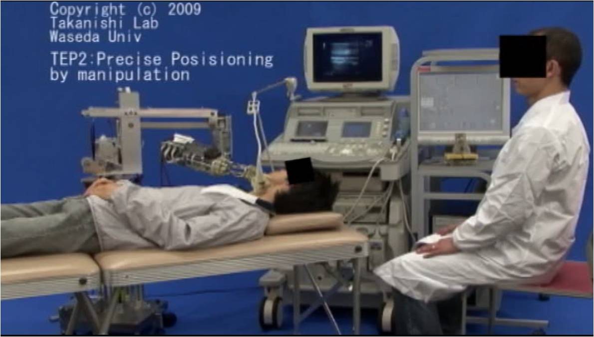
˙@)The time consumption
ü@Both the operation time for rough positioning by using passive arm an, and precise positioning by using manipulation were compared between new robot and old one. The result shows that new manipulator took shorter time consumption.

üileftüFWTA-2R,rightüFWTA-2üj
˙A)Questionnaire
ü@The result of questionnaire survey that compares new robot with old model is as the following figure.
ü@The questions were about the size, easiness of manipulator holding by hand, easiness of rough positioning, smoother motion.
All evaluation points has been improved.

üi3üjExperiment for the automated positioning algorithm
ü@The proposed automated positioning algorithm has been implemented to WTA-2R and applied for 11 healthy volunteers.
Five trials are carried out for each subject. If the whole sequence is completed without human intervention,
it is counted as "success", otherwise counted as "failed".
Sometimes the robot could not find the carotid artery and went into the roop sequence.
In that case, the operator stopped the experiment.
The result was that 91% of the trials were counted as "success".
5.Acknowledgment/Link
ü@We would like to express our thanks to Prof. Sugawara of Himeji Dokkyo Univ., Prof. Niki of Tokyo City Univ.,
Prof. Saito of Tokyo Women's Medical Univ. and Hitachi Aloka Medical,Ltd. for their daily suggestions and supports.
And also thanks to SolidWorks Corp., STMicroelectronics. and HEPHAIST SEIKO CO.,LTD for their support of CAD, software electronic components and spherical bearing.
ü@This study has been carried out under the permission of the Ethics Committee on Human Researchü@of Waseda University.
|
|
 Tokyo City University
|
|
|
 Hitachi Aloka Medical,Ltd.
|
 SolidWorks Corp.
|
|
|
|
|
| Research Introduction Page | To Home Page |
Copyright(C) 2011 Takanishi Laboratory All Rights Reserved. |