
System
Experimental Setup
We
developed an experimental setup as shown in Fig 1. The
interaction experiment between the rat and the robot is
performed in the "Open-field". "Open-field" is used in an
animal study including the animal psychology.
In our "Open-field", "Water Feeder", "Food Feeder",
"Rearing Sensor", "Grooming Sensor", "Battery Exchanger"
are located as shown.And upper two meter of the bottom,
"Fixed Camera" for obtaining whole area image and
"Tracking Camera" for obtaining local area image are
located .
The followings are details of the equipments.
Fig.1 Experimental Setup
Equipments
| Fig.2 Food Feeder |
The food feeder consists of a microcontroller PIC and a stepping motor. This machine releases a food pellet into a plastic bowl on the field when it receives an instruction sent from the PC. |
| Fig.3 Water Feeder |
The water feeder consists of a microcontroller PIC and a servo motor. This machine extends a mouthpiece connected to a water bottle into the field for three seconds when it receives an instruction sent from the PC. During these seconds only, the rats can obtain water. |
| Fig.4 Battery Exchanger |
The battery exchanger consists of a microcontroller PIC, electromagnets for attracting the batteries, 2-DOFs arm and a charger. This machine automatically exchanges the battery on the robot in the experimental field without human intervention. WM-6 moves to the front of the battery exchanger when the battery on the robot is running low. The PC then sends an instruction to the battery exchanger. After that, the arm attracts the dead battery on the robot via electromagnets and exchanges it for a fully charged battery on the charger. |
| Fig.5 Tracking Camera |
The
tracking camera consists of compact CCD camera with
a magnifying lens and the 2-DOFs camera mount. The
focal length of a lens is 16[mm], and takes a image
of locoregional area in the "Open-field" in detail. This equipment tracks the rat based on the point of rat derived by fixed camera image and takes a image of whole area in the "Open-field". |
| Fig.6 Grooming Sensor |
The grooming sensor consists of a square board 200 [mm] on each side, a base and a beam with a strain gage. One end of the beam is placed on the base, and the other end supports the board. Each strain gage is connected to an amplifier and the output of the amplifier is connected to an AD conversion board on the PC. The grooming detecting software module installed in the PC measures the voltage on the AD board and then performs FFT. Thus, this module detects grooming by the power spectrum. |
| Fig.7 Rearing Sensor |
The rearing sensor consists of photo-interrupters placed on the wall, and they are controlled by two microcontrollers. The photo-interrupters are intercepted by the rat during it is rearing. The microcontrollers then detects rat's rearing and send that to the PC. |
Experimental System
We developed an
experimental system as shown in Fig. 8. The equipments can
be classified in the following categories;"equipments for
stimulus presentation"and "measurement equipments of rat's
actions".
First, "equipments for stimulus presentation" includes
"Food Feeder" "Water Feeder" "Battery Exchanger".These
equipments communicate with Control PC using radio
communication device named Bluetooth and operate under an
command of the Control PC.
Secondly, "measurement equipments of rat's actions"
includes "Rearing Sensor" , "Grooming Sensor" , "CCD
Camera". "Rearing Sensor" and "Grooming Sensor"
communicate with Control PC by the same token and transmit
measuring result to the Control PC. The CCD Camera image
is manipulated by real-time image processor on the Control
PC.
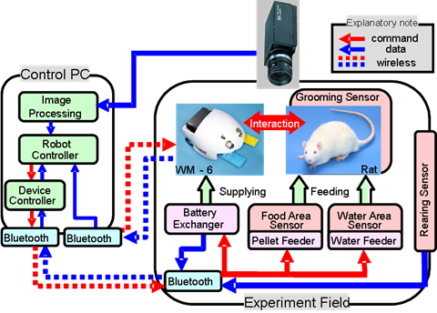
Fig.8 Experimental System
Control PC
Software
which automatically controls WM-6 and the experimental
setups is installed on the PC. This software consists of
some software modules involving image processing module,
operation generator module, robot controller module and
device controller module. This PC has two Bluetooth
communication units which support two-way communication
with WM-6 or setups. Therefore, this PC automatically
performs the interaction experiments and saves data
without human intervention.
The control PC has an image processing board, and is
capturing the images from the CCD camera. Through the
board, the image processing module computes the gravity
points of the rat and the robot respectively (Fig. 9).
The operation generator module generates the motion of
WM-6 and the operation of the experimental setups based on
the operational patterns which were programed, according
to parameters such as the robot’s position, rat’s position
and the states of each lever on the robot and the battery
voltage of the robot. The algorithm for accelerating the
rat’s learning speed is included in this module.
The robot controller module controls the motion of WM-6 by
controlling the directions and the velocities of each
motor according to the distance and angle.
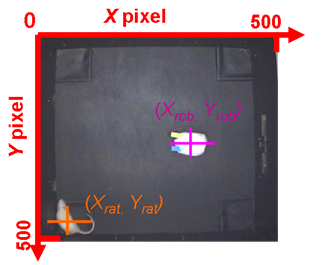
Fig.9 Image Processing